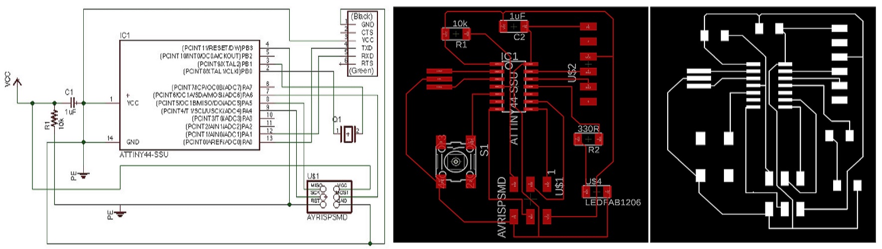
The goal of this week's assignment is to study embedded programming. The task is to read a microcontroller data sheet program your board to do something,with as many different programming languages and programming environments as possible. I studied embedded programming from different sources so that I can program my hello world board. For my Hello world board which contains Attiny44 which made by Atmel. Then I went through the data sheet of it, and tried to complete the pin out diagram of the Atmel Attiny 44, which is an eight pin microcontroller. To learn how to design a PCB, redraw an echo hello-world board, provided by Fab Academy and to add an additional button and LED, check the design rules, make it, and test it. So to redraw the echo hello-world, I had used Eagle and EasyEDA for the design. However, I have have already designed the circuit in the Elecetronics Design assignment. Here I need to programe the same and have to test for blinking of LED.
Learning Outcomes:
I first tried to read the datasheet and by step by step I found it interesting and followed the instructions of our instructor's suggestion.
Datashet for ATTINY44:
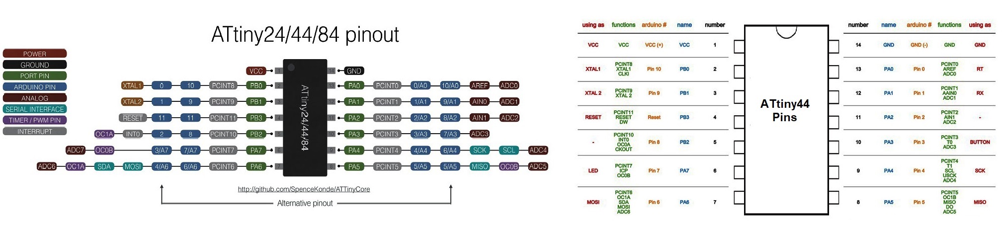
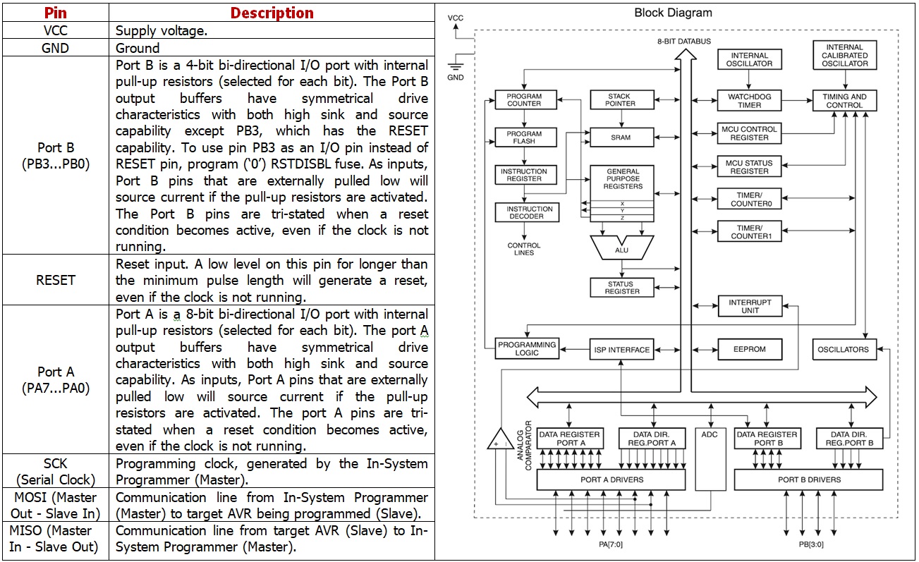
The ATTINY44 is a low power AVR® 8-bit microcontroller based on the RISC architecture.It have 12 GPIO pin's. The Atmel ATtiny24/44/84 provides the following features: 2/4/8K bytes of in-system programmable flash, 128/256/512 bytes EEPROM, 128/256/512 bytes SRAM, 12 general purpose I/O lines, 32 general purpose working registers, an 8-bit Timer/Counter with two PWM channels, a 16-bit Timer/Counter with two PWM channels, internal and external interrupts, an 8-channel 10-bit ADC, programmable gain stage (1x, 20x) for 12 differential ADC channel pairs, a programmable watchdog timer with internal oscillator, internal calibrated oscillator, and three software selectable power saving modes. The best way to know about a microcontroller and Instruction set is reading its Datasheet.we will get all the information from the Datasheet , only problem is that its not beginner friendly.
Here is Pinout schematics
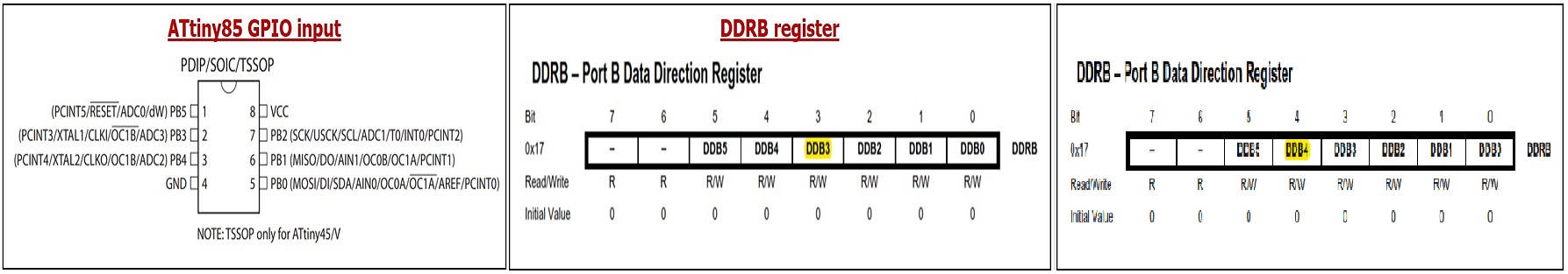
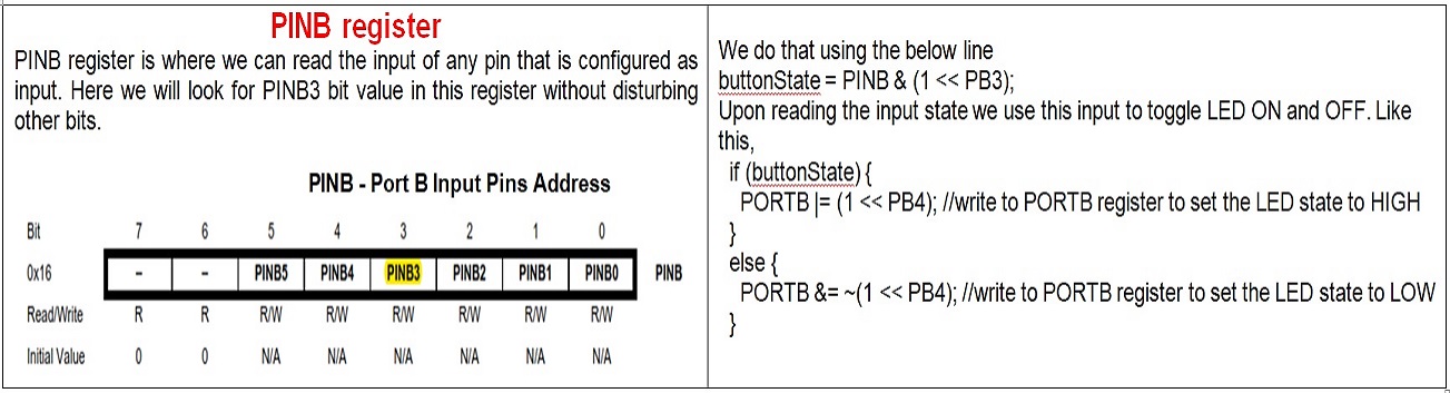
With the help of the tutorial https://www.gadgetronicx.com/attiny85-gpio-input/ I tried how to get started with this 8 bit MCU, Attiny85 and how to use its GPIO pin as an output, how to configure its GPIO pins as input and how to read status of input pin. Here I used a push button to feed signal to digital input pin and a LED as output. The LED state will be toggled based on the button input.
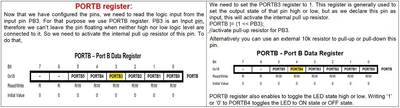
The configuration of ATTiny85 GPIO input pins starts with DDRB register, you can refer the datasheet here. I used pin 2 of ATTiny85 as Input. Now according to the datasheet the pin 2 is PB3 of PORTB. In order to make it as an Input we need to write the DDB3 register bit as logic ‘low’ or 0 in the code. The below piece of code will do that.
DDRB &= ~(1 << PB3); // Set the pin PB3 as input
Similarly we need to define the pin 3 or PB4 as an output pin. Therefore the DDB4 register bit will be logic ‘high’ or 1. DDRB |= (1 << PB4); // Set the pin PB4 as output
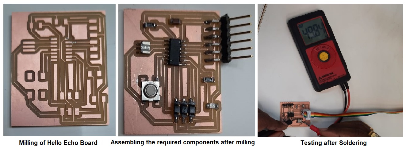
Preparing the Schematic & Board for milling
STEPS FOR PROGRAMING & CODING FOR BLINKING OF LED
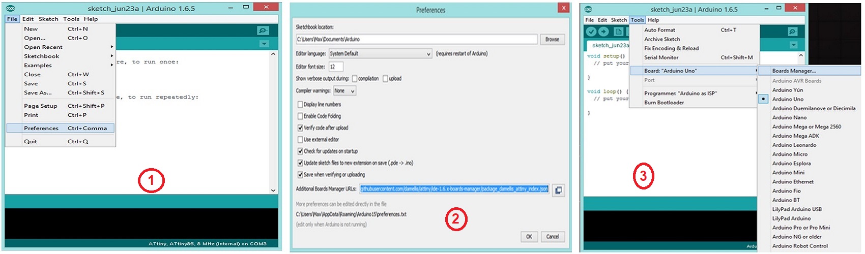
1. First of all in arduino IDE i Had to add ATtiny 44 Board to program my board:
2. Open Ardiuno IDE click File-> Prefrences
3. URL to add to the ‘Additional Boards Manager URLs’ field: https://raw.githubusercontent.com/damellis/attiny/ide-1.6.x-boards-manager/package_damellis_attiny_index.json
3. After adding the URL open Board Manager by clicking Tools >> Board >> Board Manager
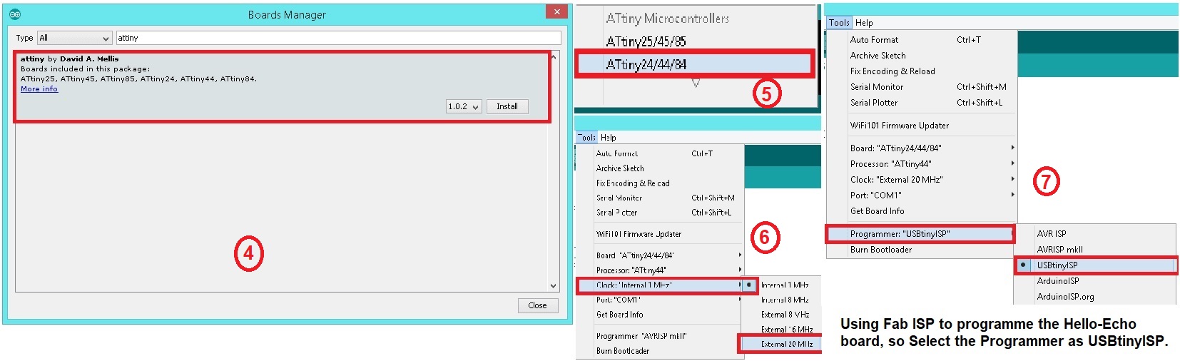
4. Search for ATtiny44 in the following Window.(Make sure you have Internet connection).and Install the latest version.
5. Now you can select ATtiny44 under the ATtiny Microcontrollers in board Selection6Select the Clock as 20MHz.
6. Select the Clock as 20MHz.
7. We are using Fab ISP to programme the Hello-Echo board, so Select the Programmer as USBtinyISP.